This is of course the area that differs the most with 550 VAR.
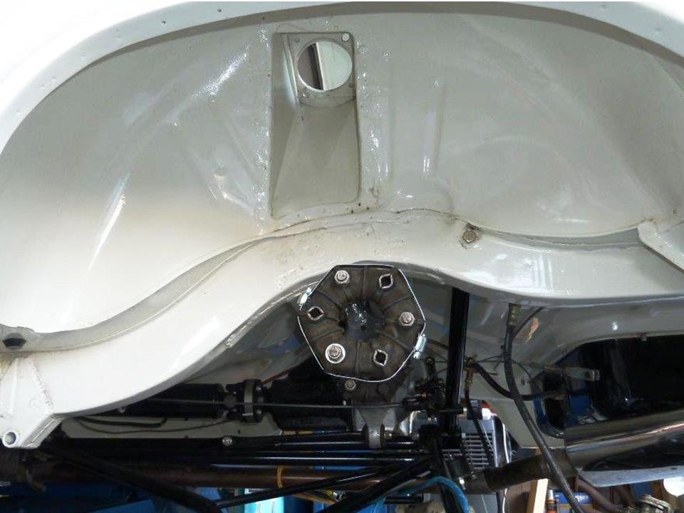
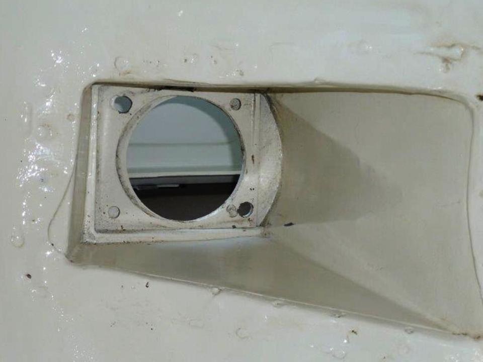
The rear wheel tubs have been extensively modified to be able to mount the Lotocones, which secure the Elan rear struts to the bodywork.
There is an extensive brace welded between the chassis rails in the line of the old back axle, within which is bolted the Elan differential.
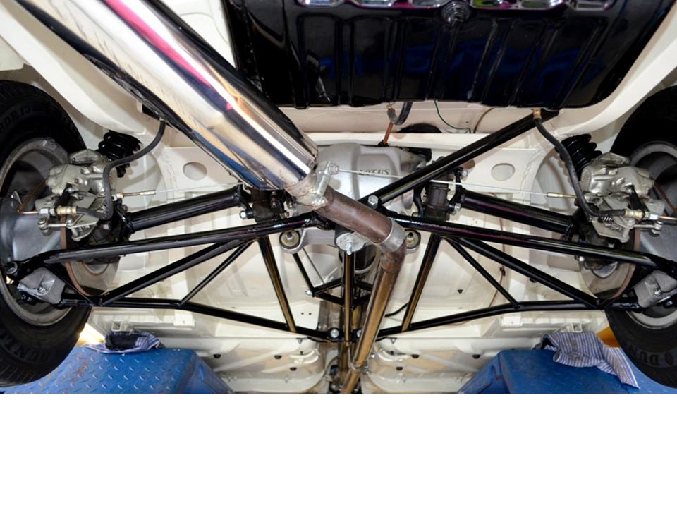
Custom built ‘A’ Frame wishbones provide the rear strut location, considerably modified from the Elan standard.
A new framework has been fabricated to provide the pivoting movement security for the differential, replacing the simple differential tie rods found on the Elan.
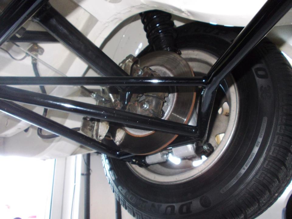
One of the first things to note is that the strengthening bars are still required as the replacement triangulation for the deleted leaf springs.
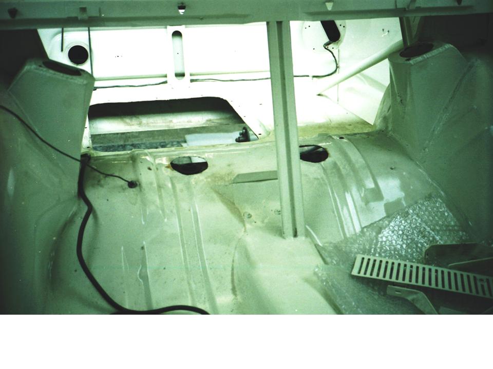
The intrusion of the strut ‘boxes’ into the boot space is also obvious.
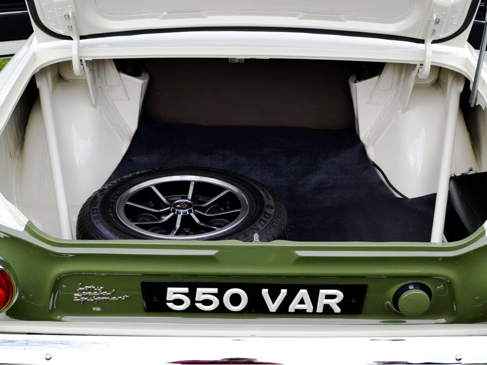
The right hand fabricated strut box
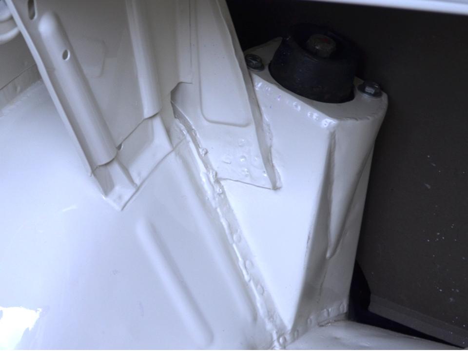
The left hand fabricated strut box
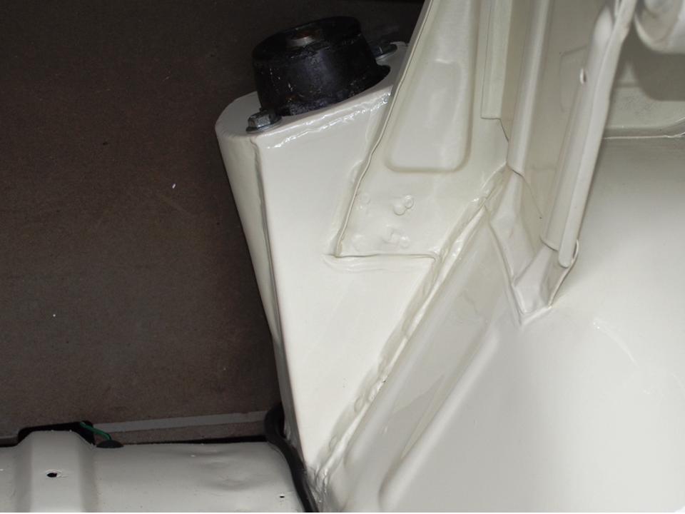
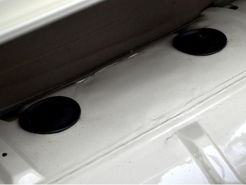
When examining Lotus Cortinas to see how authentic they are, one of the first things to examine is the differential ‘hump’ let into the boot floor. 550 VAR doesn’t have one of course, as the differential doesn’t go up and down! But you can see the ‘witness marks’ where it has been removed, and it is now flanked by the differential mounting bushes.
This picture was taken when the car was being restored by Trevor Barefoot, and shows the strut boxes from inside the passenger compartment.
Looking up inside the wheel tub with the strut removed. The top plate fabrication looks very much like a chunk of Elan chassis cut of and put in place! Note also that the rail flange has been flattened to allow clearance for the lower spring retainer on the strut, and the fabricated part of the chassis rail, fitted on all ‘A’ Frame cars, has been plated to remove the cut-out out section fabricated to clear the old back axle.
Looking up into the Lotocone mounting plate.
A photograph taken when the car was being restored, giving a good overall view of the suspension layout.
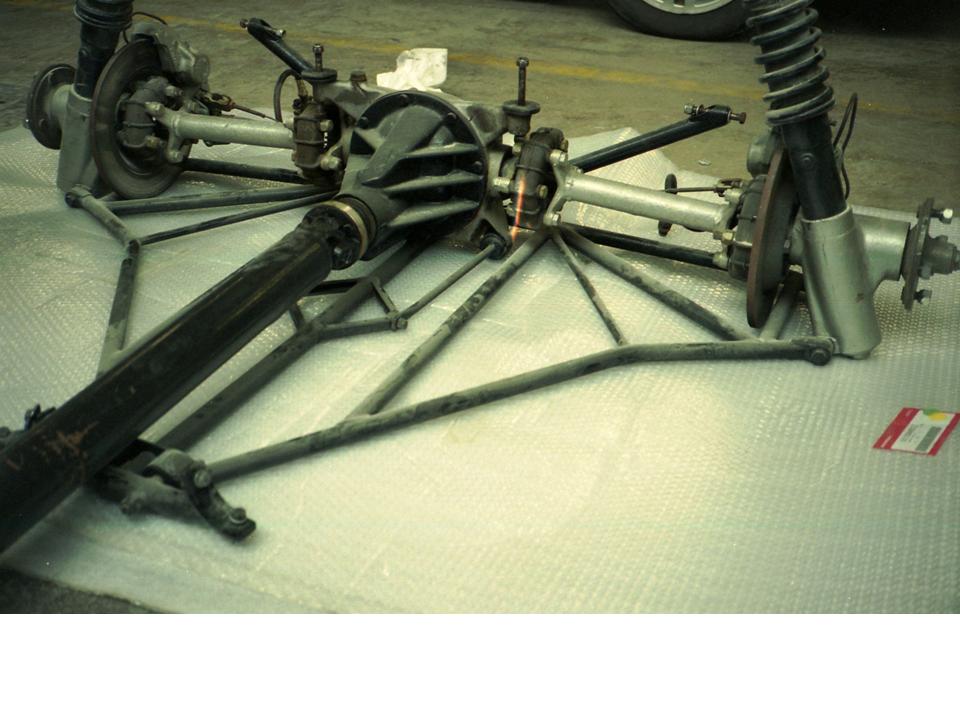
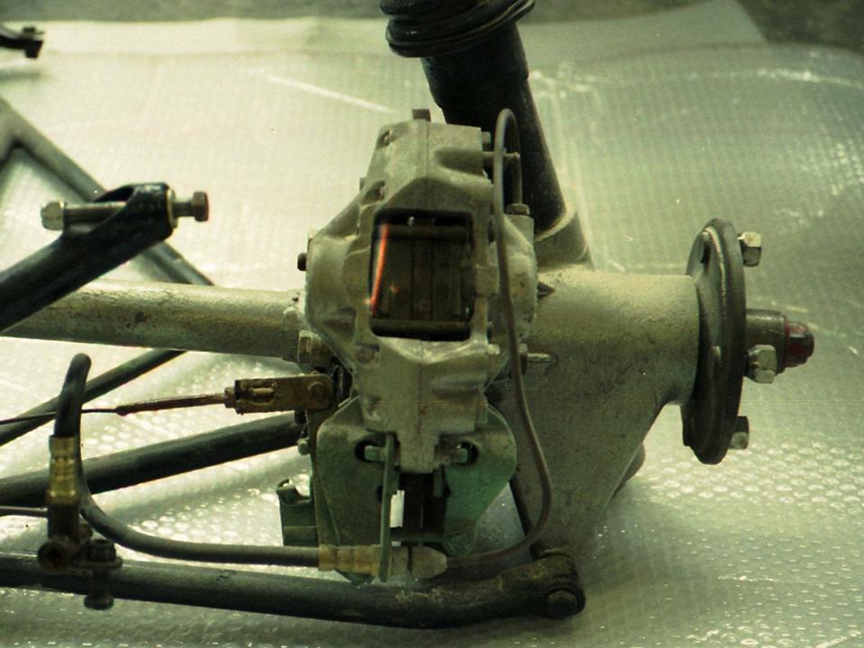
The right hand hub, showing the Elan rear calliper and handbrake mechanism.
The complete rear suspension setup in place.
Left side detail
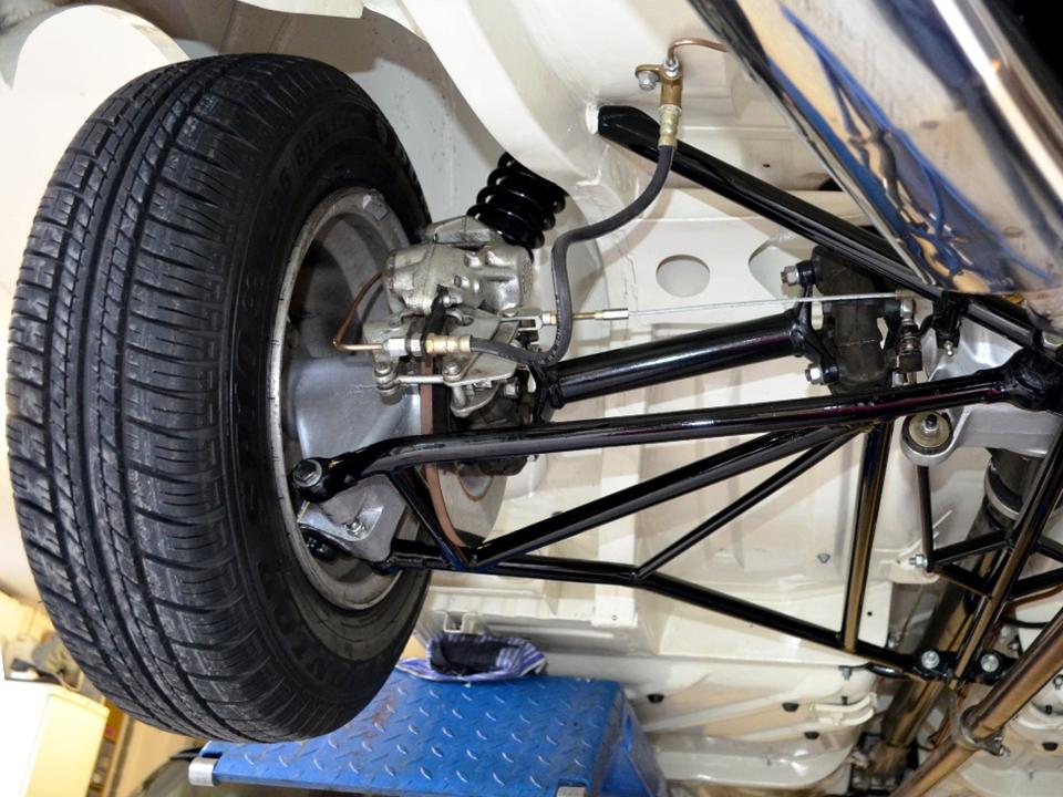
Right side detail.
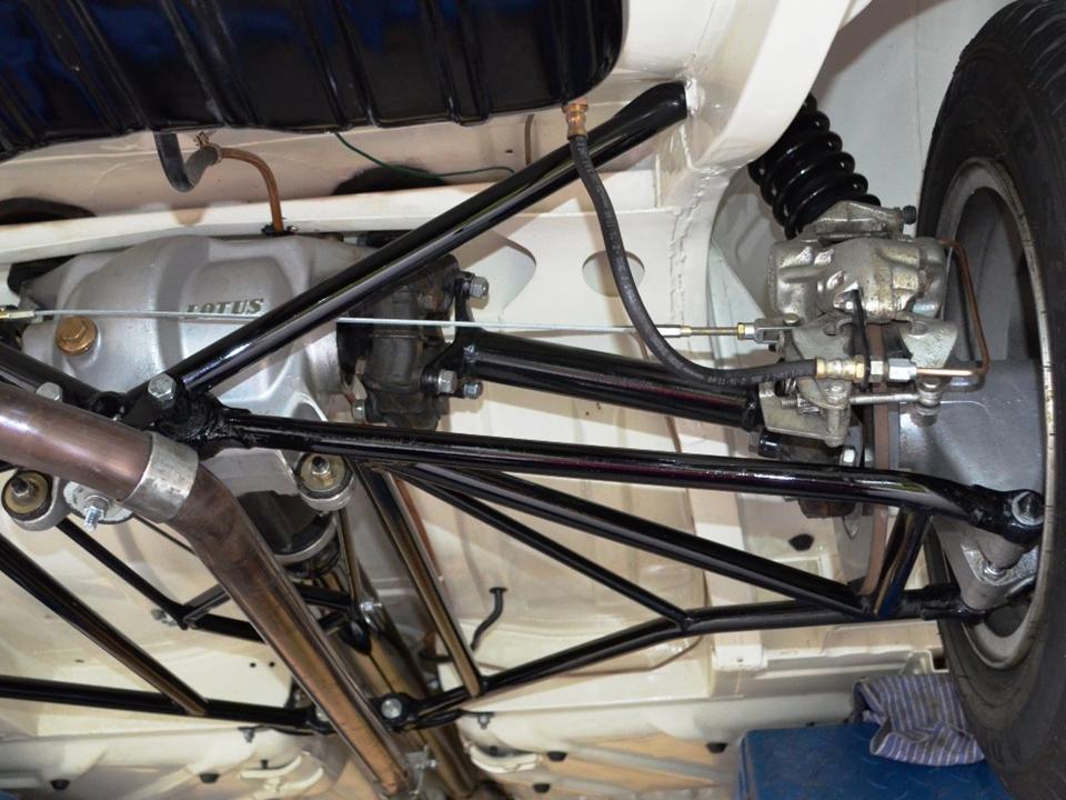
Rear / inner wishbone mounting detail.
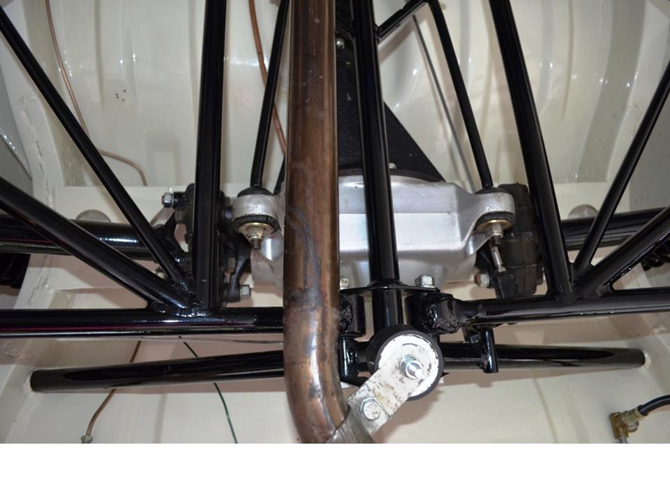
Differential tie-rod mounting to central fabrication.
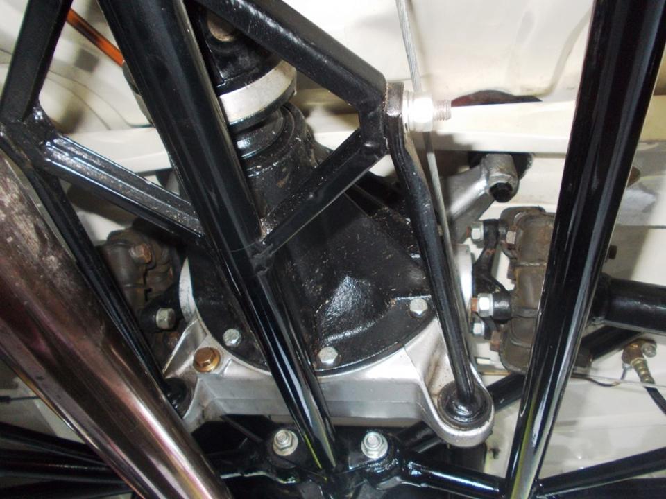
The front of the central fabrication showing it’s fixings to the floor pan, and the front inner wishbone fixing to it.
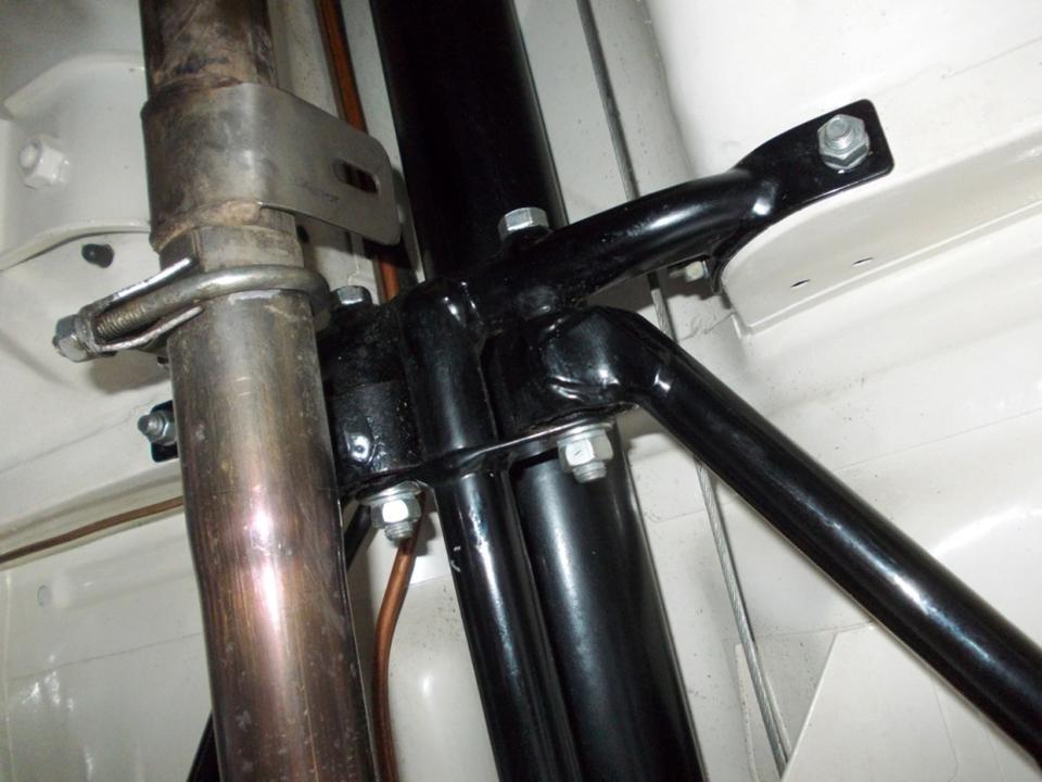
A view from the front showing the left hand hub and disc.
